Grbl Controller Usb Driver
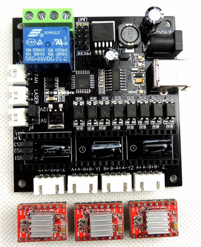
Grbl Controller Usb Driver Code Chicken Core Naskah Drama Ktoprak Moon Elongation Angle Download 3ds Max 2017 Update 1 Antares Autotune 7 Vst Crack Minecraft Dayz Mod Twrp Para Root Samsung Galaxy A8 Open Source Moodle License Sm-g900x Firmware Download Darkavenger X Apk Mod Walk In Shower Floor Options. USB GRBL 3 Axis Stepper Motor Driver Board Controller Laser CNC Engraving + Case - $44.93. 3-axis USBCNC control panel, miniUSB interface, 3-axis limit, manual low light, can 17. Stay tuned!First, to connect your stepper motors to Grbl, you'll need some stepper motor drivers to power the steppers and connect your driver inputs to the Arduino controller pins. There are a number of drivers that can do this, available as fully pre-built, partially pre-built, or completely DIY.
GRBL Axis CNC Controller Offline 1.8 inch USB Driver Board for Engraving Machine For Sale
GRBL Axis CNC Controller Offline 1.8 inch USB Driver Board for Engraving Machine:
$30.08
GRBL Axis CNC Controller Offline 1.8 inch USB Driver Board for Engraving Machine Features: 100% brand new and high quality Manual control: Manually adjust the positions of the three XYZ axes as the starting point for engraving, and manually turn the axis on or off. Recording file: GRBL control board can be connected to recording board after the file is saved in offline, no need to connect to computer. Storage file: Offline version is recognized as a USB mass storage device after connecting with computer, and can directly access the recording file . Upgrade to update new firmware to increase high-speed speed, compatible with SD card. Long press Z+ on main page to change language. Specification: Material: Plastic Size:As Picture Shown Color:White Model: 1.8 inch handle offline screen Power supply type: plug-in power supply Power supply voltage: 110V Input power: 100 No-load speed: 10000 (rpm) Package Includes: 1x Offline Controller note: 1.Please allow 1-2cm errors due to manual measurement, make sure that you do not mind before you order. 2.Due to the difference between different monitors, the picture may not reflect the actual color of the item. Introduction: How to Flash GRBL Onto GRBL CNC Controller Board (CNC3018, CNC1610, Etc)
How to Flash GRBL Onto GRBL CNC Controller Board (CNC3018, CNC1610, Etc)
Having trouble with your GRBL board? GRBL is commonly used with many DIY CNCs and some 3d printers. Firmware on the boards can get corrupted, and while the boards are usually fairly cheap, there is often no need to replace them at all. The process is extremely simple, and requires very few parts.

What you need: https://www.amazon.com/VEVOR-Machine-Control-Exten...
Cnc Usb Controller Software
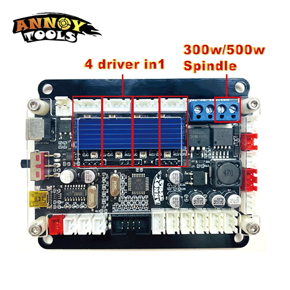
1. GRBL Control board (Annoy Tools, Cronos, Woodpecker, etc)
2. An AVR programmer board. I used a USBTinyASP clone, but there are many of them
-If you don't have one, one can be had from Amazon for less than $10. Click here for the one I use or here for more
3. Dupont connectors - for this, you'll need female->male, but it's usually cheaper to just buy them in a kit with all the variations, plus its always good to have them on hand for prototyping, replacements, testing, etc.
4. a computer
Step 1: Step 1: Get Your Supplies Together
Before starting, you'll need to download the GRBL firmware you want to flash.
Here's a link to GRBL v1.1. Save the hex file into an easily accessible folder, you will need it, as well as the folder directory later on.
Get your GRBL/ CNC Controller board off the cnc and get your avr programmer and wires.
Once everything is at hand, and prior to plugging anything in, connect the female dupont connectors onto the ISP port of the avr programmer you're using.

Step 2: Step 2: Connect the Leads to the GRBL Board
The next step is to connect the leads from the ISP port to your board.
Luckily, the 'Annoy Tools' board that came with the CNC 3018 has a marked ISP port. You may have to do some digging to find specifics for your board, but worst case scenario, you can use the pinout of the ATmega328p, and connect as directly as possible. You need to connect:
VCC, GND, MOSI, MISO, SCK, and RST
These are connected directly - ie VCC -> VCC, etc. The AVR programmer should have either a pinout labeled on the board itself, or if not, readily available online. Some boards have more than 6 connections, in that case, ignore the rest.
Since the ISP port is simply an array of vias/holes in the pcb, its possible to lose connection if left straight.
An easy remedy to avoid disconnecting is to put something fairly heavy, like a wrench, over the wires to hold a slight amount of pressure in turn keeping the connectors still, and in contact with the pcb. You can also solder connectors onto the ISP port, but since you shouldn't need to do this very often, it may be easier and more efficient to just apply some pressure.
Step 3: Step 3: the Programming..
This is the 'hardest' part. It's not hard, but you have to know what to put into the command prompt.
First thing to do is to open the command prompt. On Windows, simply type CMD into the start search and the command prompt will pop up.
For this step to work, you need to navigate to the directory where the hex file for GRBL is.
To do this, you'll want to go to that folder where the hex file you downloaded earlier is, and copy the 'address bar' or simply note what it is, and write it
1. Open notepad/some text editor
2. Go to the folder where the GRBL hex file you saved earlier is
3. Copy the directory address -- ie 'C:UsersYourUserDocumentsGRBLFolder'
4. Open the command prompt and navigate to the directory address you just copied by typing 'cd ..directory..':

ex: 'cd C:UsersYourUserDocumentsGRBLFolder'
5. Now copy and paste the following command line into notepad/text editor:
'avrdude -patmega328p -cusbtiny -Pusb:bus-0:.libusb0-0001--0x1781-0x0c9f -b19200 -Uflash:w:grbl_v1.1h.20190825.hex'
The command string you'll need will vary depending on your programmer, computer, and file. Here are some tips to figure out the string you need to use:
a. 'avrdude' - stays the same, don't change this.
b. '-patmega328p' will be the same as long as the board you're using is using an ATmega328p. If its using another atmega board, simply enter that boards command, available in the link below.
c. '-cusbtiny' is the command for the USBTinyISP. This command depends entirely on the programmer you're using. For example, if you're using a USBasp clone, you'll use: 'usbasp-clone'. Regardless, you will need to enter some form of '-cYourProgrammer', a full list of boards is available in the webpage linked below.
d. '-Pusb:' is the serial port or bus connection. If using a serial port, you can simply enter '-PCOM#' (#=your port). If not, you may need to find your bus address in the device manager (you can also find your COM port # in the dev mgr)
e. 'Uflash:w:' Enter the exact file name of the GRBL firmware file you downloaded earlier after 'w:'
*To find your specific commands, if using another programmer or another board, check this link for a full set of avrdude commands.
6***. After constructing the correct command, copy and paste the constructed command into the command prompt, (and make sure it is still directed to your GRBL folder containing the hex file) and press enter.
You should see 'Reading' then 'Writing' then 'Reading' again, and finally 'Done.'
7. If it has successfully Read/Write/Read, then you have successfully reflashed your board! If you get an error, see below:
*** If you got an error along the lines of 'AVRdude is not a valid command', then you do not have avrdude installed/correctly configured to a path. Luckily there is a super simple workaround to this, all you will need to do is place the avrdude files into the same folder as the hex file, and if not using a serial port, the USB driver as well.
7b.
a. Simply download and place the following files into your GRBL folder (ignore the other files in the picture) alongside the hex file:
-avrdude.exe
-avrdude.conf
-libusb0.dll
[I can't remember where I downloaded these, so I shared the files directly. If anyone has a Github/direct link, please share it in the comments and I will add it.]
b. After placing these files into the GRBL folder, repeat step 6, and you should have success.
c. After successfully uploading GRBL firmware, unplug the programmer and wires from the ISP port, reconnect the GRBL board, and test out functionality with your preferred CNC controller software.
Happy CNCing!
Edit Log:
(8/12/2021: formatting, grammar, clarity)
Jeremy Laratro

Be the First to Share
Recommendations
Cnc Usb Controller Driver.exe
Metal Contest
First Time Author Contest
Backyard Contest